EagleCAD and Advanced Circuits
UPDATE I have posted an automated tools for gerber export here UPDATE
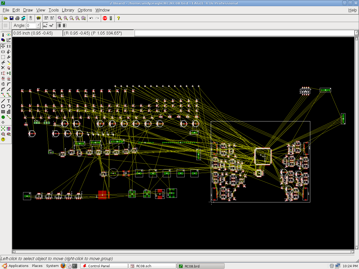
So congratulations! You just routed 3000 nets and placed 250 components! You are probably going a little crazy, seeing things that could be placed more efficiently and thinking about how you would route them. Well you’re not out of the woods yet! You’ve got at least another few hours of generating gerbers, panelizing them and passing DFM, and you’ve got a few hours of finding and ordering all the components on your parts list.
These notes are relative to EAGLE CAD and Advanced Circuits (including 33each/barebones). The instructions follow for most other board houses.
I’ll talk about gerbmerge in another post.
Passing DRC
This should be no big deal because you have been regularly checking DRC (Design Rule Check) in Eagle right? This of course requires that you have a properly setup DRC file for whatever process you are using. You can get mine for Advanced PCB (and 33 each) here. They allow 6 mil trace width, 6 mil spacing and 15 mil minimum drill size.
Of course, when routing a board, do not use the minimum trace widths and spacings unless you have to! There is no sense in pushing their manufacturing process if you don’t need to. Thinner traces and spacings may get fargled up in fabrication and you may have electrical errors.
Generating Gerbers
First, in the command line, run drillcfg to generate a .drl file. This tells the manufacturer which drill bit to use for which hole size. Some manufacturers only have a certain list of drill sizes they support, you can edit this file (carefully) such that the drill sizes match which drills which are available.
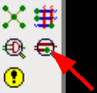
Next, create excellon drill files by clicking file -> cam or press the cam button. This will open the CAM processor. The cam processor turns the board layout into instructions for a numerically controlled machine (NC).
To generate the drill files, from within the CAM dialog, select file -> open -> job. Select excellon.cam. Press process job. This will generate .drl and .drd files.
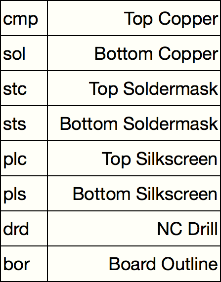
To create Gerber files for Advanced circuits, download advance.cam and place it in the Eagle CAM folder. From the CAM dialog, go to file -> open -> job select advance.cam. Press process job. This generates .cmp, .sol, .stc, .sts, .plc, and .pls files.
If you prefer to use 33each (which is only the top and bottom copper) use this cam file.
Use gerbv to preview those files. Make sure that none of the layers are mirrored or flipped. Zip up the above list of files and submit them to freedfm to check your files for manufacturing problems.
When the report comes back and you’ve fixed all the errors, you can choose to submit those files for manufacture or you can submit them to another manufacturer. I prefer using 33each (an Advance Circuits deal) for quick prototypes.


