Vaisala RS80 Radiosonde Teardown
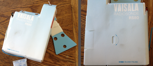
An interesting piece of gear passed across my desk, a Viasala RS80 Radiosonde. The RS80 radiosondes is a small electronic payload which is typically lofted into the upper atmosphere by a helium filled balloon. During its journey, it relays to the ground (or records) environmental information, such as barometric pressure, temperature, and humidity. Its location is determined through GPS.
Radiosondes are interesting pieces of gear, on one hand, they are fundamentally disposable – as such, must be very low cost; on the other, they are specialized pieces of scientific equipement – something which typically demands top dollar. Since they are lofted into the air by (now costly) helium filled balloons, they must be as light as possible. Because they are typically not recovered, they must not contain hazardous materials such as heavy metals (see the odd battery). The payload may encounter extremely low temperatures, and large temperature gradients due to radiative heating. These extremes cause trouble with temperature sensitive components such as electrolytic capacitors and crystals.
Teardown
This particular model is the RS80-15GH, according to this datasheet the ’15’ suffix denotes a 405Mhz transmit frequency, the ‘G’ denotes a GPS receiver, and the ‘H’ denotes the H-HUMIDICAP option, a humidity sensor.
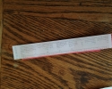
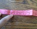
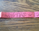
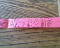
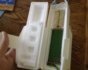
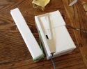
Opening the hermetic bag reveals a cardboard and styrofoam encased radiosonde, a spool of string, a bag of desiccant, and a short piece of punched tape. The tape, below, presumably contains calibration information about the various sensors in the radiosonde. Fascinating, I’ve never seen paper punch tape in person. Looks like a byte every 1/8 of an inch or so.
Peeling back the right side of the unit reveals a helical antenna attached to a shielded GPS module. The upper board, with the helical antenna, is soldered to a fairly thin RF can. This is probably the thinnest RF shield I’ve ever seen in a product; they’ve done everything they can to save weight. That said, the can completely covers the module, and is well grounded with a large bead of solder. Removing the can takes some effort, but I make short work of it with my shiny new JBC iron (a graduation present to myself).
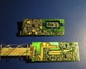
The top board can be removed after desoldering the can and a seven pin 0.1 inch header (upper right). This reveals a piece of foam that I unfortunately melted a bit while desoldering the can. Lifting off the foam shows a rather large crystal oscillator. This is an ovenized crystal!
Crystal oscillators are fairly temperature sensitive; 10-20 ppm per degree Celsius is a typical figure for such oscillators. In a radiosonde, the temperature of the oscillator could vary as much as 50°C as the payload goes from room temperature in an office or lab to the upper atmosphere. Worst case scenario that’s 1000 ppm! To make things worse, that crystal is certainly multiplied up by a few factors to downmix the GPS carrier – so the 1000 ppm drift could be multiplied as well! To mitigate this, the designers ovenized the oscillator – controlling the temperature to minimize drift. Heaters tend to burn power though, a precious resource on battery operated electronics, so the crystal oven is well insulated.
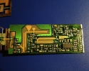
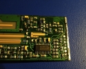
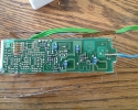
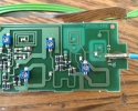
In the sixth picture, the GPS antenna frontend is shown. The antenna elements feed a stripline which is capacitively coupled to a pre-amplifier in a “helicopter” package characteristic of RF transistors. The passives surrounding the transistor make up its bias network. The skinny snaking trace is an inductor in the bias network.
After the amplifier, a number of RF structures couple the signal to what appears to be a diode mixer. The GPS signal is mixed with a LO, produced by the MC145201F, a 2.0GHz PLL frequency synthesizer, in the 20 SOIC.
Notice, there appears to be no ability to completely decode the GPS signal in the radiosonde. Reading its datasheet, the GPS IF is mixed with the transponder carrier and transmitted to the base station for decoding. This design reduces the part count, cost, and power consumption of the radiosonde – at the expense of a more complicated base station.
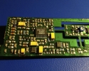
The board with the ovenized crystal is chock full of analog stuff. Several op-amps, tons of passives and a few SOT-23 transistors. Note, all high value capacitors are tantalum, not electrolytic. Presumably some of the circuitry is for temperature control, perhaps others for filtering the GPS IF. Note the prominent custom ASIC labeled Vaisala GPS2. It’s difficult to speculate about precisely what goes on inside this part, though it’s clearly part of the GPS subsystem.
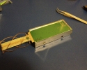
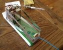
Turning the unit over and peeling back its cardboard shell reveals a temperature sensor on a silvered flex PCB. The flex and the temperature sensor are mirrored to reduce the effect of solar radiation on temperature measurements. The temperature sensing element is the tiny silver bead in the second picture. It is designed to be as tiny as possible to reduce its thermal mass so it can rapidly respond to changes in temperature.
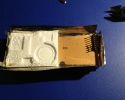
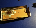
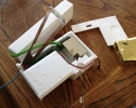
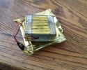
Underneath the temperature sensor whip is the battery – the gold and gray rectangle in the fourth picture. The battery is also sealed in a hermetic foil package, and according to the datasheet, is water activated. It’s important to remember that since the unit is disposable, it should contain a minimal amount of toxic materials such as heavy metals – thus the battery electrolyte is water based. That said, I’m not sure what happens when the battery is exposed to extreme temperatures. Interestingly, the battery is terminated with a conventional 9V battery snap.
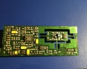
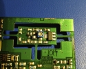
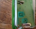
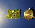
When the battery is removed, the cardboard and foam casing can be removed revealing what I would call the main circuit board. The most prominent feature of the main circuit board is the large blue monopole antenna. The monopole is flanked by two triangular stamped metal pieces which presumably form the ground plane of the monopole. A number of RF inductors (spiral shapes) linked by variable capacitors flank the area around the monopole antenna. A large plunger type tuning capacitor can be seen in the sixth picture. This capacitor is externally accesible presumably for tuning. The upper area of the circuit board is where the other sensors and GPS are integrated.
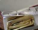
Above the battery, in a shielded can connected to the main circuit board is where the sensor conditioning circuitry lives. This is where the temperature sensor whip is terminated. Inside a EMI shield lies an odd can. At first, I thought it might be a cosmic ray detector, two plates charged to a few kV, that breakdown every so often in the presence of a charged particle. In fact, this appears to be the HUMIDICAP option. This is a humidity sensor. The sensor is capacitive, when the external air pressure is increased, the plates move together, decreasing the capacitance of the sensor. If I were interfacing with this sensor I’d probably build an oscillator with the capacitor. The changing frequency of the oscillator could then be mixed with the LO and transmitted as FM humidity information – but it’s probably converted to a voltage and digitized.
This is an interesting bit of gear, lots to learn.

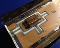
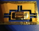
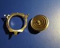
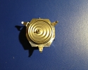
Andy, you describe an “odd can” , which appears to be a capacitor sensor based, “aneroid barometer”, and the device looks like a typical aneroid barometer. These radiosonde devices usually send information on altitude. What makes you think this is a humidity sensor, rather than an aneroid barometer?
Tim
Ah! Yes I stand corrected. That’s clearly a capacitive barometer. Sealed can with bellows, capacitive plates attached to the bellows. As the external pressure increases, the bellows allow the plates to move together, increasing capacitance.
I used to work for UK meteorological office 1979-1996. The RS80 superseded the UK MK3 Radio Sonde. Originally the balloons were filled by hydrogen, but this was replaced by helium when the radio sondes operations became a one man operation. (Hydrogen deemed to be too dangerous for solo-operations).
Balloons would regularly reach 100,000 feet and would exceed 120,000 feet in summer months.
The GPS RX was used to determine the physical location of the antenna and trigonomtery used to calculate wind speeds as the RS made it way upwards through the tropospehere/stratosphere.
A small parachute was attached between the RS80 and the balloon to effect a controlled descent when the balloon burst at altitude.
The paper tape did contain calibration information for the radio sonde. The sonde calibration was verified immediately before launch by comparing the telemetry values with ambient conditions.
The ground station was a Pentium 386 PC with attached paper tape reader and interface to the UHF receiver.
The version I used did not use GPS, but had a built in Loran receiver.
Regards
The Humicap was under the small thimble just next to the temperature sensor.
The batteries were water activated so they would haev a long shelf life. I believe they are Zinc-Air cells (like hearing aid cells) but not sure.
The devices also have to be small and frangible to minimise risk to air traffic. Every year they get smaller with the current RS41 (2014) being a pretty device that needs almost no prep to send away. It has short range radio for communicatng with the ‘ground check device’ and self heats the humidity sensor to reference it to dry before launch and prevent possible icing in the upper atmosphere under extreme conditions.
Good stuff on Wikipedia and the further reading links.
https://en.wikipedia.org/wiki/Vaisala
This is a great article, I just brought one of these sondes to play with the GPS from ebay, now I see how you stripped yours down I’ll be sure to open mine carefully. If anyone else wants one heres the link to the item page: http://cgi.ebay.co.uk/ws/eBayISAPI.dll?ViewItem&rd=1&item=400980264286