NI USB-6009
So I was handed a National Instruments USB-6009 and I had to tear it down.
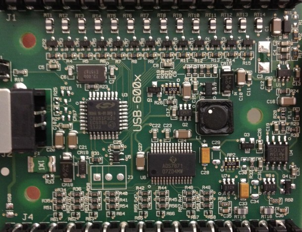
It’s a fairly nice four layer design, with only a few major components. The board is marked USB-600X and there is an un-populated header – can a USB-6008 be easily upgraded to a USB-6009?
On the right, we see a USB B connector and a single indicator LED. There is a whole mess of unpopulated passives around the highspeed USB traces. They must have been concerned about signal integrity issues.
On the top and bottom of the image, there are two large screw terminal connectors. The top (in the image) port is designated “Digital” and the bottom port is designated “Analog”.
The “guts” of the 6009 are the following two parts
- SiLabs C8051F320 an 8051 core USB microcontroller with a whole ton of peripherals.
- TI ADS7871 a data acquisition system-on-a-chip.
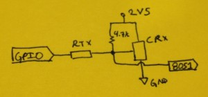
On the top, “Digital” port, from the left to the right, are pins P0.0-P0.7, P1.0-P1-3, PFI0 (trigger interrupt), 2V5, 5V, and GND. The GPIO and trigger interrupt pins all have a similar analog front end which is connected directly to the 8051.
The engineers at NI did an excellent job on the silkscreen of the board, but looking at it, some of the markings leave me puzzled. Take a look at the analog input schematic. The passive in series with the input signal is marked RTx. Perhaps it’s an NTC thermistor? The SOT-23, three terminal part has CRx silkscreen markings. I’m thinking it might be a dual diode package. This part is also unpopulated on the USB traces.
Active components are marked Ux. U1 appears to be the 2V5 linear voltage regulator. U2 looks like a switching power supply controller for the 5V line.
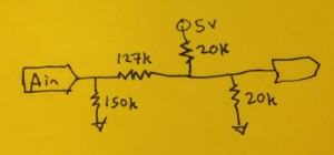
On the bottom (in the picture) “Analog” port, the analog inputs are interspersed with ground pins. The analog inputs all also have a similar input structure (pictured above). They appear to be simple voltage dividers. Strangely the 150K pull-down resistor is 0402 while the others are 0603. The topcodes are strange for resistors also. Maybe a commenter can share some insight. The analog inputs (after their front-end) are all connected to the TI DAQ-on-a-chip part.
The NI USB-6009 also has two 12 bit 150S/s analog outputs on the lower right of the image. Around those two pins are grounds, and on the board there are a cluster of passive and active components. The signals presumably come from the TI part, but I’d have to get out a meter to check. U4 is a dual opamp and the other SOT-23-5 packages are presumably single opamps.
There is some other strangeness. What is part FL1 (on the far right opposite the USB connector)? What is R50? Why is it way over there? That’s a pretty serious trace-width for an un-populated part. Look at the traces near the letter “U” in USB-600x. Why do they go out of their way to put them adjacent to one another?
All told, it’s a pretty nice piece of hardware, I’ve had better luck with Labjack parts – much much better open source support, but the NI USB-6009 isn’t bad when you’ve gotta use Lab View.


Do you know the part number for U1? I need to replace mine. Thanks, Phong Le
I’ll have a look at the board, but offhand to replace U1, something like a Microchip TC1014-2.5VCT713 should probably work. I would use a meter to probe around the pins on the board a little. I can see pin 1 is VCC (5V), but is pin 2 gnd? Not sure. What is pin 3 connected to? It should be connected to VCC also (or at least something positive not GND). Good luck!
Microchip TC1014-2.5VCT713 with Pin1 = Vin, Pin 2 = Gnd, Pin 3 = EN, Pin4 = ByPass, Pin5 = Vout. If you see pin 1 = Pin 3 = 5VDC, Pin2 = GND, and Pin5 = 2.5V, then you are correct on the part number. Can you verify it for me?
Thanks,
Phong Le
Do you know the part number for U7- D12N? what’s the fuction ?Thanks,Duan
Duan, U7 and U8 are most likely single OPAMPs for each of the USB-6009’s analog outputs. If you study the picture, you can see a RC output network with a NTC resistor for protection.
Out of curiosity, why are you interested? I assume the firmware for the 6009 is loaded at runtime, with a schematic and discussion (as I’ve provided), one should be able to build a reasonable clone 🙂
Thank you for your reply, I am a graduate, I have recently used the NI-6009. Out of curiosity, so I open the equipment , and begin to study the circuit of the NI-6009. Suddenly I find the NI digital to analog conversion is very special, I think U7 or U8 is a digital to analog converter, because it is connected to the SCLK, DIN, and it is controlled by P2.4 or P2.5. Do you agree with me.?Our discussion is just out of interest and not involving commercial secrets.I also particularly interested in your research, I am also doing four rotor, I hope I can get your technical support, thank you very much!
Huh. I looked at it again and you’re right Duan! From TI, http://www.ti.com/general/docs/topsidemarkingformats.tsp If you search for SO-23-6 with top code D12N, you get that the part is a DAC7512N, a “Low-Power Rail-To-Rail Output 12-Bit Serial Input DAC”. Thanks for the feedback!
Honored to have your reply,I hope I can get your advice ,thank you!
Hi, I just opened my 6008, and the only difference I see is an ADS7870, instead of the ADS7871 – Do you think just replacing this part will upgrade the 6008 ?
I suspect there is a firmware upgrade that would be required to upgrade the 6008 to the 6009… That said, I think the firmware is loaded at runtime, and downloadable from NI. At runtime, the software looks at the USB ID (possibly stored on U5) then loads the appropriate firmware. With some work you should be able to upgrade it.
i am caught up between the NI-6009 and labjack U6-Pro..which one do you think i should buy,better one and why?
I tend towards LabJack products because their language support. In a sense, the decision is easy: if you’re planning on using LabView – get the NI product, if you’re planning on programming in any other language (python, matlab, java, c, c++ etc) get a LabJack.
What does the digital output front-end circuit look like?
CR is a common reference designator for a diode. And the package marking 44t is from NXP for a BAS40-04 Schottky barrier diode.
RT is a common reference designator for a therminstor.
I see that you are more familiar with labjack products. Did you ever had the change to do a teardown of a labjack product?
Years ago I took apart a U12. I remember an all-in-one TI ADC/DAC (maybe a ADS7807) and a Microchip PIC (I think). I remember noting that the I/O came from *both* the TI part and the microcontroller. Some analog lines on the uP were used. This was probably six years ago though..
i need the name of U4
i need the name of U4
http://www.ti.com/product/TLC2262
I andy one question i have two USB 6009 OEM with failure i check and both have the two chip with damage my question is possible change this two chip for example the USB microcontroller i think need some program right and the other is only a converter please let me know of you know something
Thanks. What analog front end circuit for inputs do? Why that resistors and 5V is over there?
The resistor network at the analog inputs is for dc biasing the ADC input. It shifts the input voltage up to half the ADC input range. this way it can measure negative input voltage.