Keithley 2000 DMM Repair
I’ve been shopping around for a nice bench DMM for a while now, so I bought a busted Keithley 2000 off Ebay thinking that it would be an easy repair. I assumed that all the input protection in a modern DMM should fail first to protect anything important, and all I would need to do is replace it (maybe a few MOVs, a fusible resistor etc).
What’s interesting is all the input protection appears fine, but the meter is still damaged!
Keithley is kind enough to publish a repair manual, but it seems they have gone through great lengths to obfuscate the circuit as much as possible, while still offering a glimmer of hope to a third-party repair person. There are no schematics, but rough descriptions of the circuit operation. There is a parts list, but a few of the parts (in particular the JFET SNJ132199 – more later) are obfuscated behind in-house part numbers – even though they are standard parts.
Symptoms
When the meter arrived, I first checked the fuses (power fuse fine, amps fuse vaporized) and cracked it open to see if there was any visible damage (burnt components, vaporized traces etc.). The unit seemed pretty good inside, so I plugged it in, and with nothing connected to any of the terminals, none of the functions appeared to work. Actually, some of them were working, but because of the meter’s auto-ranging, they all appeared broken. Also, at this point, I didn’t try to connect anything to the meter, because it all appeared broken – if I had, I would have discovered that in fact, some of the functions were operational.
One nice thing, is the Keithley 2000 has a whole suite of built in test functions accessed by hitting the <TEST> button. I ran the built in tests, and I got the following error codes;
- 302.1 – 2W Sense
- 302.2 – 2W Sense
- 400.2 – Non Inv Path
- 402.2 – Non Inv /10
- 403.2 – Non Inv Bex2
Ok, that’s a lot fewer error codes than I thought there would be, but it’s a start. Let’s look at the manual which describes each of the tests and the components involved (I interpreted the manual incorrectly – but more later). I made a list of the components involved in each test so I can work through which ones might be bad.
The two 302 codes both involve the same circuitry, and from other tests, and probing around, I got the following list.
- R272 – ok, 301.1 passed
- Q109 – ok, 301.1 passed
- R117 9.9M – ok, 301.1 passed
- R115 | R324 | L109 – ok, could not really test L109
- R113 –
- R107 – ok
- R103 – ok
- R108 – ok
- K101 – ok, 301.1 passed
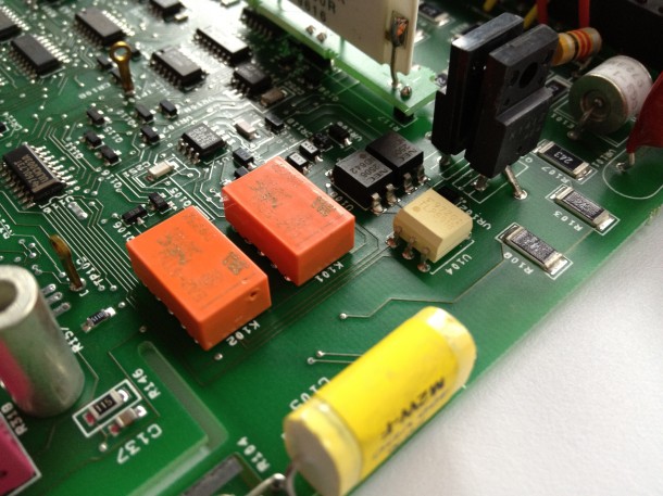
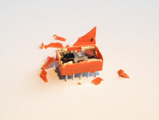
- K102 – dead, hole in side of package!?! charring inside
- Q105 –
- U113 – ok, 301.1 passed
K102 Relay
Wait, what! There’s a hole in the side of K102, a small signal relay!
Wut…. So I desoldered the relay and tested it out on the bench. The manual reminds me over and over not to be confused by its operation – it is a latching relay.
In the off state, it is in the “set” position – at power off it should be “reset”. Clearly broken. So I gave it a pulse to the reset pin, hear a muted clicking, but the relay remains “set”. Busted. Time to take it apart.
I jumped the pads for the relay so it was “reset” powered on the meter and ran the self tests again. My reasoning was, even if there were new errors, if the old tests passed, the relay was the only culprit.
Re-ran the tests, failed test 401.2 and 402.2. Good. Now I only need to troubleshoot error 402.2 Non Inv /10. Time for bed.
Mystery JFET
So, I left the lab far too late last night and left the meter on overnight. It was in the 10VDC scale, and leveled out at around 3.079V. This is with the K102 relay removed, no jumpers installed.
WTF, the DCV tests passed. What is going on here? So, I jumped K102 to the “reset” position and applied 1V to the DMM input. The meter reads 1V no problem. Hmmm…
What if I mess around with the DCV scale? With the voltage source removed, in the 100V and 1000V scale, the meter reads 0V. The lower scales are all wonky.
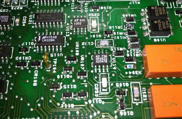
Looking at the “Analog Signal Switching States” table in the repair manual, I narrowed down the devices in the signal chain which are different between the 10V and 100V ranges. I traced the 1V signal through the chain, and Q108 does not turn off completely. But it’s a mystery JFET.
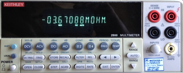
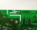
Let’s have a look at the 2 wire Ω signal. Now, ohms ranges 1MΩ and below are fine, 10MΩ are totally off (see title photo). Tracing the signal through, Q109 does not turn all the way on.
Ok, no problem. I’ll replace the JFETs. According to the parts list, Q108 and Q109 are both listed as “TRANS, N CHANNEL JFET, SNJ132199(SOT-23)”. So Google only produces this thread. According to this post, Keithley also suggests
- Interfet SJN132280
- Fairchild Semiconductor 5149B51374A
- Fairchild Semiconductor 5149_NB51374B
Which all don’t exist. But according to that thread, the top mark was “132” while the top mark on my JFETs is “6G”. Google says that top mark “6G” on a N JFET is a MMBF4393LT1. Bingo. FETs and relays ordered.

Hello!
Can you help me ?
I have similar problem with my Keithley 2000. Self-test failed (errors 600.1,600.2,601.2).
It is Ohm/Amp faults according Repair Manual.
What do you think, which IC needed to be replaced?
thank you!
I’m still debugging my 2000 – and now I have a second 2000! Seems that it IS working, just that some component is out of spec (damaged?) in the high impedance ranges (10G!). What I’m gonna try next is to simply replace components till it starts working. Then I’ll have to figure out how to calibrate it. The other 2000 has a different problems. Seems there may be something physically wrong with it, but someone tried to recalibrate it, now it thinks that it’s A/D is broken – but it’s not, just the cal values are wonky for one particular test. I donno, I got a 34401a, and I’m pushing though my thesis now, so this is kinda on the back burner.
Hi! Any update or progress on your unit? 🙂 I got 2001 myself and in fixing progress as well 🙂
It’s very different from 2000 tho, but more interesting prolly 😀
I opened repository and uploading files/photos etc on my site, if want take some part – feel free to contact 🙂
http://dev.xdevs.com/projects/kei2001/repository.
BR
Ilya
Ilya, do I need to register for an account to view your repository? Good luck!
how to browse the repository? I can’t see any files.
I got 2400 and 2000 to repair and need schematics. My relays and FET are in good shape. I am pretty sure both 2400 and 2000 were destroyed with high voltage at the input (they were working on an ESD setup-high voltage, kV). Does anyone know what can be broken ???
Are schematics available somewhere???
No, to view repository and download files no need any registration, this is free public project.
But if you want to do more than just read data, maybe get involved that to register will allow do so better.
I can create Keithley 2000 subproject too, I just don’t have any.
Creating “repair” project with project managment seem to be little bit overkill, but I just used to use my development tools already available to make it easier 🙂
I understand using dev tools – nearly every one of my projects lives in a GIT repo. Makes it easy to collaborate, and versioning is always great.
Ilya, I made an account, still I cannot view photos and schematics in the Keithley 2001 repo :/ Help?
Strange, http://dev.xdevs.com/projects/kei2001/repository/show/photos section is public available, even without any registration, few guys already were able see it without problems.
Added you to project team anyway, just to make sure 🙂
Iliya, there is a strange message now: “The page you are looking for is temporarily unavailable. Please try again later.”
Hello Andy, did replacing those fets solve the 400.2 error. I am considering buying a keithley 2000 with that error hopefully for a cheap price.
Regards Richard
We’ll it’s more fixed than it was, but still a little broken. I’m gonna post again.
ello,
I have two flawn Keithley multimeters:2000 and 2015THD. For the 2015THD I would need the content of the two memories of 27C020 ( U156 , U157 version B07 ). It starts when I put the memories from 2000 but i don’t think it is working in the normal parameters…where could I find the memory content? I am willing to trade the Keithley 2000. For the Keithley 2000 I have found the following errors when I run an internal test:
101.2
101.3
200.1
200.2
201.1
201.2
300.1
301.1
301.2
302.1
302.2
303.1
303.2
304.1
400.2
401.2
402.2
403.2
500.1
500.2
600.1
600.2
601.2
Do you think that there is a possibility for reparing the Keithley 2000? Maybe with a scheme…but I didn’t find one! I could really use some advise from more experienced peers in the field!
At Keithley 2000 I measured all voltages after repair manual is within the tolerances , reference voltage of 7V (U141 LM399 ) which I suspected is 6.98 , the more I replaced several of the analog IC’s (mux-u163, u165 ADC, u113, u115, u129, u166, u132 operational amplifiers) but errors not disappeared . At the same IC’s Keithley 2015 functions without error , or something I’m missing and do not know what , any idea is welcome.
Thank you
Costas
Hello,
I acquired a defective Keithey 2000 where the AD converter U165 is missing altogether. It was probably removed in an earlier repair attempt.
What is the part number that you used and where did you get a replacement for U165? U165 is not mentioned in the partslist in the repair manual.
Thank you,
Paul
—
Paul, unfortunately the Keithley 2000 “ADC” U165, is a programmable logic device. In very old Keithley 2000 models, the U165 is in fact an Altera EPM7160. Presumably they use a similar ADC scheme as the revered HP 3458A. This technique is documented in the excellent April, 1984 HP Journal. Really worth a read.
Andy,
My Keithley 2000 DMM also broke recently. The built-in test indicates it is in the ADC section. I found the repair manual annoying – a “tease” manual that leads one to think that the circuit diagram will be provided but stops short with much talk about the circuit but leaving the troubleshooter in the dark as to what is being probed. I will never buy a Keithley product again. Agilent provides circuit diagrams and their DMMs would consequently be far easier to maintain by the user.
As an engineer who has designed test equipment for Tektronix in the past (starting at Tek when I was 17 years old), I am now (much later) designing open-source instruments and am inviting others to participate. See my website at http://www.innovatia.com I hope to form arounf this effort a community of users, builders, entrepreneurs who want to become suppliers, and even fellow designers.
It would be a major task to reverse engineer the Keithley 2000 but somebody ought to do it and post the results on the web, not only to help people with broken units but also to send Keithley (now part of Tektronix) the message that NOT providing circuit diagrams is NOT some industry standard, as they claim on their website. i have done this for some consumer-oriented power electronics that is not open-source.
In my open-source instrument program (set of projects) at Innovatia (which is me) I do not have any DMMs, though it would not be hard to add one if anyone is interested. I wouldn’t mind starting with people on your site here who are trying to fix already-designed DMMs and forming a community to do our own completely transparent DMM – maybe 4.3 digit (20000 count). I am doing this with related instruments that might be of interest to DMM fixers. Take a look at my website. Currently, I am developing a two-port analyzer (curve tracer, or dual SMU) that can make some DMM measurements and more, such as amplifier gain, transistor beta, etc.
Dennis, thank you for sharing your project. Unfortunately, it seems that schematics in repair manuals have all but disappeared – the most recent Agilent (Keysight?) DMM service manual with a schematic is the 34401A (now obsolete).
Best of luck with your project!
Hi Andy,
I would like to acquire a broken Keithley 2000 which does not power up.
With almost no experience in repair and no schematic do you think I stand a chance of repairing it?
Or should I go for a broken Fluke?
I suspect you have experience in repairing stuff.
Thank you.
hi,
I know this is an old post, but someone corrected errors 600.1 600.2 601.2
Thank you
Dear Andy,
Thank you for your SNJ132199 alternate reference ! I finally found that NJ132 was interfet process used to produce… 2N4393 !
You can have a look at my K2000 repair story at http://dedius.free.fr/index.php?post/2014/11/06/Keithley-2000-repair
Regards,
dEdIUS
@dEdIUS fascinating story, thank you for sharing!