Flying Android Project
In 2009, I was challenged by [govt agency] via GTRI to develop an Unmaned Aerial Vehicle (UAV) which is piloted by a smartphone. In particular, only the sensors on the phone may be used and the flight controller must run on the smartphone. Custom electronics were allowed to interface the phone to the airframe (PHY) but those electronics could sense or control. In the fall, with a team of a few friends, JP de la Croix, Brian Ouellette, and Paul Varnel, we met their challenge.
Overview
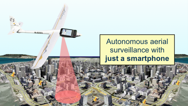
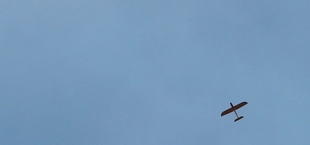
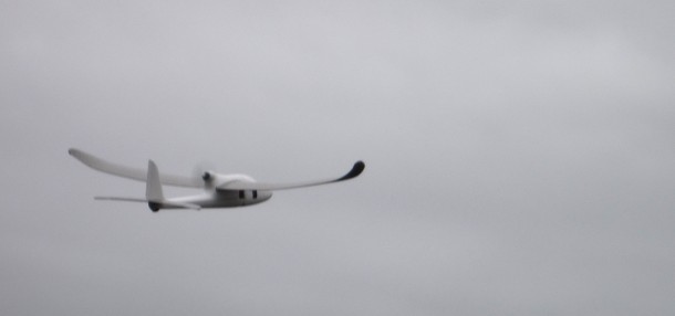
The Flying Android Project aimed to design and fabricate software and hardware systems needed for a smartphone to autonomously fly a small, inexpensive, unmanned aerial vehicle. The software running on the smartphone guides the aircraft autonomously using exclusively onboard sensors. The software loads the GPS waypoints from a file and directs the vehicle to travel to each waypoint. The phone can receive updated waypoints and control parameters via SMS. When the plane reaches a waypoint, it captures desired sensor readings such as images and network information. The plane can operate for at least 15 minutes before it needs to land and recharge. The cost of each vehicle is approximately $900. The vehicle is based on the Android powered G1 developer smartphone and the Multiplex EasyStar aircraft. The smartphone interfaces to the flight hardware using a serial port via a heavily modified ArduPilot board. During testing, the vehicle demonstrated the ability to fly stably to waypoints and collect and report sensor (e.g. image, wi-fi) data.
Hardware
We spent some time discussing which smartphone we would develop with. We considered phones based on Windows Mobile, iOS, Nokia Symbian, and Android. We chose Android because it was the easiest for our team to develop on despite having lower performance hardware (at the time only the G1 was available).
The heart of the system is the G1 Android developer phone, a smartphone manufactured by HTC which runs the Android operating system. The developer version of the smartphone is the same as a retail T-Moble G1, but it is software unlocked (rooted) and will accept any SIM card (unlocked). The phone has a 3-axis accelerometer, a 3-axis magnetic compass, GPS, and a camera. It can communicate via GSM, WiFi, and Bluetooth.
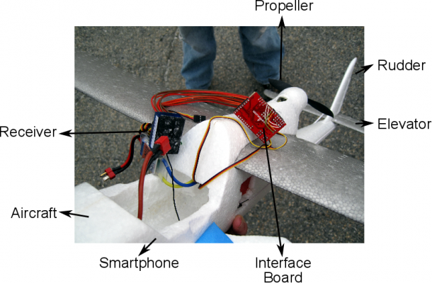
The smartphone was integrated with a Multiplex EasyStar ARF Electric RC aircraft. The aircraft has two control surfaces: the tail elevator and the tail rudder. The elevator is controlled by a single servo and determine the pitch of the aircraft. Pitch determines whether the aircraft will gain or lose altitude. The tail rudder is used to control the yaw of the aircraft. A second servo moves the tail rudder left or right, which causes the aircraft to turn in the same direction.
It’s interesting to note – particularly for those just starting out in robotics or control theory – the aircraft can explore it’s entire six-dimensional workspace (x, y, z, yaw, pitch, roll) – despite only having three control degrees of freedom (elevator, rudder, throttle).
Thrust was provided by a pusher propeller driven by a Himax HC2815-2000 brushless motor. A Multiplex MULTIcont BL-17 ESC was used to drive the motor.
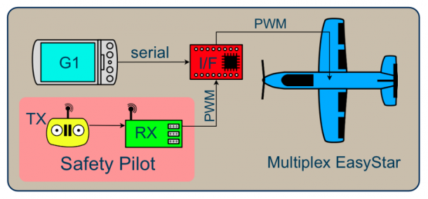
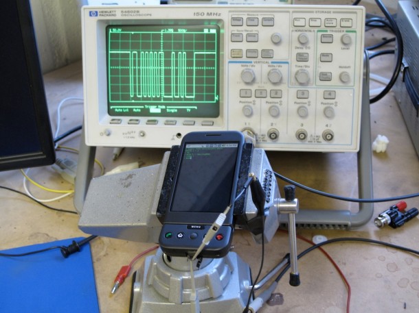
The servos and motor (through the ESC) are connected to an interface board with a microcontroller based on the ArduPilot. Software on the microcontroller was designed to convert the serial motor commands from the smartphone into PWM signals for the motor and servos.
An HTC ExtUSB 11 Pin USB Connector was used to connect both pins to the interface board. The smartphone sends commands through the serial line to the microcontroller on the interface board. The serial signals from the phone had to be amplified from 2.5 volt serial logic to 5 volt TTL signals to interface to the flight hardware.
A RC safety pilot receiver was also connected to the interface board to provide a fail safe in the event of control failure. The RC safety pilot unit received signals from a 2.4GHz DSM (Digital Spectrum Modulation) transmitter operated by a pilot on the ground. A 5-channel transmitter uses four channels to control the aircraft, leaving the fifth channel open for custom use. When the fifth channel was activated, the interface board ignored commands from the smartphone and used the PWM signals from the safety pilot to fly the aircraft instead. The safety pilot not only provides a fail safe for when the smartphone fails, but was also used for assisted takeoffs and landings.
Software
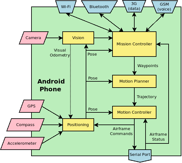
System software architecture. Each square box is a software component that runs in its own thread. Octagonal boxes represent inputs and outputs to and from the device.
The flight controller was designed to send signals to the airframe control surfaces and propeller to keep the plane on the path generated by the path planning system and stabilize the aircraft. It used the same flight dynamics models as the positioning system along with the position data for accurate control. Proportional-integral-derivate (PID) controllers were used to stabilize the aircraft in flight.
The mission controller handled all of the high level details for a particular mission. In the case of the primary mission of GPS waypoint navigation and photography, the mission controller read the predetermined GPS waypoints from a file and sent them to the path planning system. It also sent requests to the vision system to take pictures when the plane reaches each waypoint. In the future, the mission controller may communicate with the ground station.
The positioning system calculates the most likely position of the plane using the combined reading from all of sensors which measure position, including the GPS, accelerometer, compass, and feedback from the flight controller.
The path planning system generates followable paths between the GPS waypoints using the flight dynamics model of the plane and send the paths to the flight controller.
Controls
All software, with the exception of the C code translating from serial to PWM and arbitrating between auto and manual control, was written specifically to run on our Android-based smart phone. Affectionately called “DroidPilot”, this software was responsible for stabilizing the platform in the air and navigating to GPS waypoints during the mission.
Stabilization is achieved through PID controllers driving the error to zero between the current roll and pitch and their set points. Ignoring navigation at this time, the set points are zero, such that the controllers will try to drive the system to level flight. Roll and pitch are sensed through the combination of two sensors on the phone–a three axis accelerometer and a three axis magnetic compass.
Most autopilots use either thermopiles or gyroscopes; however, the current generation of Android-based smart phones do not have such sensors built in. Unfortunately, accelerometers are very sensitive to vibrations. We observed that turning on the throttle in the aircraft would induce mechanical vibrations that dramatically increased the noise-to-signal ratio. Therefore, we combined information from the magnetic compass and applied a filter to the accelerometer measurements to offset the mechanical vibrations.
We implemented a first order infinite impulse response (IIR) filter, which filtered out most of the new measurements in favor of older measurements. While this approach reduced the amount of “jerkiness” on our control surfaces, it also slowed the response of our controllers to changes in the aircraft’s configuration in the air.
Given the substantial amount of noise in our system, we eliminated the derivative term from our controllers and strictly used PD control. We considered implementing either a PI-Lead controller or an adaptive controller; however, given the time constraints on testing, we opted to fine tune the PD controllers.
The navigation module is responsible for choosing the pitch and roll set points based on the aircrafts current location and the next waypoint. It is also responsible for controlling the throttle to maintain altitude. Waypoints, in the form of GPS coordinates, are given to the autopilot ahead of time.
In addition to stabilization and navigation, the autopilot is also able to take ground imagery using the smart phone’s camera at a given interval or when entering the area surrounding a waypoint. Each image taken was not only tagged with EXIF data, but also GPX data, which correlated images to GPS coordinates. After landing, the images can be transferred from the SD card on the phone to a computer and uploaded and integrated into Google Earth.
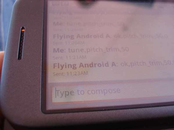
Finally, the application also includes a UI for changing the control parameters, which can also be changed via SMS.
Reflection
During testing, the system demonstrated stable flight while navigating between waypoints. In addition, during development, the ability to modify control parameters (programmatically and via text message) was frequently exercised. Due to stringent FAA and FCC requirements, testing opportunities were rather protracted. As such, the tuning process was painful and time consuming.
This project was very challenging due to the requirement that onboard sensors are used exclusively. The greatest challenge was imposed by this restriction was the lack of airspeed sensing. This severely hampers the effectiveness of our controller because the effectiveness of the control surfaces is directly proportional to the vehicle’s airspeed.
In addition, the onboard sensors suffered from poor signal-to-noise ratio. The accelerometers in particular were very sensitive to vibration (severe vibrations from the powerplant on our vehicle). In retrospect, this project would greatly benefit from a high fidelity physical model. The physics model would partially mitigate the need for airspeed sensing and significantly relieve our need for physical testing.
Even if the flight testing could not be executed virtually, none of the developers were skilled pilots and thus had little “intuition” and could not serve as the safety pilot during testing. Having a pilot on the development team would have greatly aided the design process.
Future Work
While the results presented during this project are positive, much work remains before this platform can be considered production worthy. In particular, adding a high-fidelity flight dynamics model to the positioning, motion planning, and motion control components would likely improve the overall performance of the UAV in several ways. While incorporating these changes into some portions of the application may be rather trivial, in other areas this would require a major overhaul. Once the model is derived, it could be added incrementally to the software to allow testing of each change.
In addition, in the future we would like to add support for other Android phones. Since the inception of this project, several Android phones with improved sensors and processors have been released. For the purposes of this project, the G1 was chosen for it’s serial communications, but this may not be available on other phones. It may be possible to use the USB port available in all Android phones, but in order to communicate with the micro-controller (USB slave) we must use USB On-The-Go (OTG), which is not natively supported by the Android operating system. It may be possible to implement USB OTG drivers, but this will probably require a significant development effort.
There is a possibility that the phone could communicate with the flight hardware via bluetooth. This approach is undesirable because it adds both the potential for wireless interference and increased complexity in the embedded hardware.
The most likely approach to enable multiple phone communication is via the headphone jack. On every Android smartphone, there is both a microphone and headphone jack. These ports provide a theoretical bandwidth of 60 kilohertz out of the phone and 30 kilohertz into the phone. An additional benefit to this approach is that it requires no extensive modification to the phone operating system allowing conventional application deployment. Unfortunately, this slightly increases the complexity of the hardware which acts as a bridge between the phone and the vehicle.
Regardless of operating system, it should be possible to port Flying Android to other smartphones with similar hardware specifications, however, this would require significant development effort.
In addition, another area of further research is into autonomously takeoff and landings. This would further reduce the demands on the user and make the system safer and more robust. Autonomous takeoffs and landings should be fairly simple given flat environments, but could be dangerous in places covered with trees or hills. Given the robustness of the platform, the vehicle can withstand quite rough landings though it would have to land somewhere that the operator can retrieve it. A forward looking camera and obstacle avoidance algorithms could mitigate this, but would take a significant amount of development of both software and hardware.
In order for this app to be used in a real deployment, several features would need to be added. All of the communications to and from the phone should be encrypted, including data link and safety pilot. Since the platform is designed for personal use, key exchange can be done by direct connection to the phone. It would also be desirable to fully support functioning in GPS denied environments; currently it can only handle short periods of GPS dropout. This could be added by implementing visual odomety, or some other secondary localization system.
Finally, there is the possibility to expand this development modality into other robotics arenas such as underwater and ground vehicles. These vehicles would take handily to this approach as they have far less stringent sensor and processor requirements. All told, this is a promising direction for rapid robotics development and should lead to many exciting developments in the near future.
Acknowledgements
We are deeply indebted to our academic advisor Dr. Whit Smith, our GTRI advisor Dr. Mick West, Dr. Tom Collins who interfaced between GT and GTRI, our safety pilots Dave Price, Gary Gray, and Brandon Vaughn, Tim Lewis and his team at the Ft. Benning Maneuver Battle Lab, and our sponsor the DARPA Rapid Response Technology Office.


Very interesting article.
I would like to know how this work can be passed to NOKIA 808 that has a superb 41mpixel camera and all the necessary recording devices you describe in your article(GPS accelerometers compass). I know that you have to transfer your software to Symbian.
I would like to know an approximate cost in money and time of such a solution.
My best regards
Yannis Yanniris
MSc Photogrammetric Engineer