SeaWolf
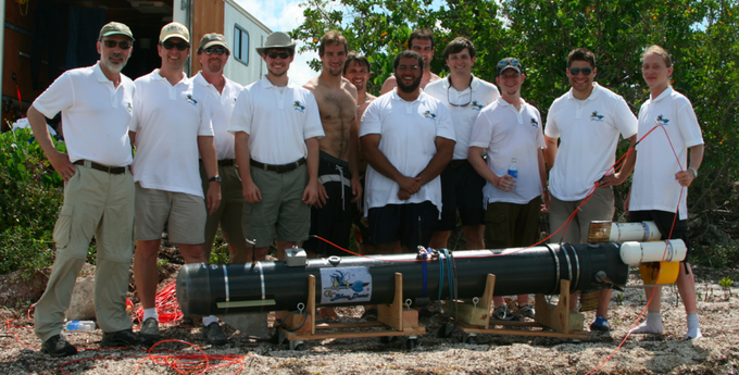
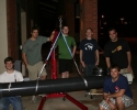
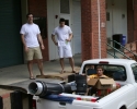
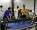
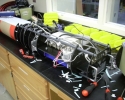
During the Spring and early Summer of 2009 I developed two 10.5 foot long, 325 pound unmanned underwater vehicles (UUVs). My role was technical leader, I oversaw all design of the vehicles.
Underwater vehicle construction remains somewhat of a black art where effective design principles are often found through trial and error rather than analytically. This page serves to document the design of our vehicles so others can learn from our experience.
Design Requirements
When complete, the system should be able to transport a 36 inch long, 8 inch diamater, 100 pound payload to a 100 by 50 foot target from a minimum range of 500 feet with a minimum speed of 10 knots.
Overall Design
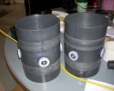
The requirements necessitated a quite large vehicle. To achieve the desired velocities, we chose to develop a “torpedo like” vehicle. The completed vehicle was roughly 10.5 feet long and weighed nearly 325 pounds.
For the purpose of organization, I will start my description of the vehicle at the nose and work rearward.
All internal modules ran on a guide rail (McMaster# 3310T243).
Hull
Nose
The nose of the vehicle is a 10 inch diameter schedule 40 clear PVC endcap from ClearPVCPipe.com owned by Alsco Industrial Products which is located in Atlanta. We intended to mate the end cap to the hull – 10 inch diameter schedule 80 pipe also sourced from Alsco – with common PVC cement.
Turns out schedule 40 fittings do not mate properly with schedule 80 pipe. The inside diameter of the schedule 40 cap was about 0.125 inches larger then the outside diameter of the schedule 80 pipe. PVC cement cannot effectively fill gaps. In fact, when we tried to bond the parts together after a long all-nighter, only some small patches bonded – the “dark” spots – while there were large air gaps – the “light” spots.
After a few hours of sleep, we returned to the lab to prepare the vehicle for a pool test. Well a few of us (author excluded) became convinced the glued portions were actually the light patches and the unbonded air pockets were the dark patches. We all wanted to desperately believe this was true, but ust setting the vehicle on the surface of the water showed our error – the vehicle began to leak.
We banged the cap off with a large PVC rod and a hammer and epoxied it to the hull with around four tubes of Devcon 8-12 minute expoxy (McMaster# 7541A77). That suff was excellent, we used it prolifically all over the vehicle – though it does not seem to be suitable for potting things.
While epoxying the nose cap to the hull, we discovered getting the epoxy even was a real challenge. Vibrating the curing parts and forcing epoxy in to the gap with a scraper helps a little though the best solution would be to vacuum out the hull and suck the epoxy in.
Payload
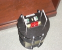
The payload module was constructed similar to the other modules in that it had two waterjetted plates (PVC for some ABS for others) connected by threaded rod with a spacer.
An AXIS 206 webcam was bolted to a plate attached to he front of the payload module. Above the payload module were four hull intrusions for (in order from front) the pressure sensor, debug connector, fiber box, and the emergency stop.
Hull Intrusions
There were four hull intrusions above the payload module (in order from front) the pressure sensor, debug connector, fiber box, and the emergency stop.
The pressure sensor was a SSI Technologies P51-51-A-B-I36-4.5V-R from Digikey (DK# 734-1046-ND). We used a six pin SubConn connector as a serial debug port. SubConn connectors seem to be overrated for their price. The connector is an overmolded rubber part that mates with waiting pins and locks using a cheesy plastic shroud.
The SubConn part numbers were
- Bulkhead connector – MCBH6M $67.70
- 100ft wire with connector – MCIL6F/100FT $260.44
- Bulkhead plug – MCDC6F $10
- Locking sleeve – MCDLS-F $8
After talking with the guys at GT Savannah, they showed us Bulgin Buccaneer connectors which have versions with RJ45, USB, Firewire, and SMA. They are available at Digikey.
Fiber
The fiber was a bit of a kluge. We couldn’t afford – the price or lead time – of a military grade or commercial UUV tether. So we bought some COTS “water block” fiber from UltraSpec Cables. The cable was 600ft long with at SC (square) connector on one end and a ST (round) connector on the other.
The ST connectors mated inside the “waterproof” (Home Depot) NEMA double gang box which was screwed and bonded to a flat machined on the outside of the hull. We joked that we would fill the box with grease if it leaked. The boxes stayed dry – tested to 25 feet.
Emergency Stop
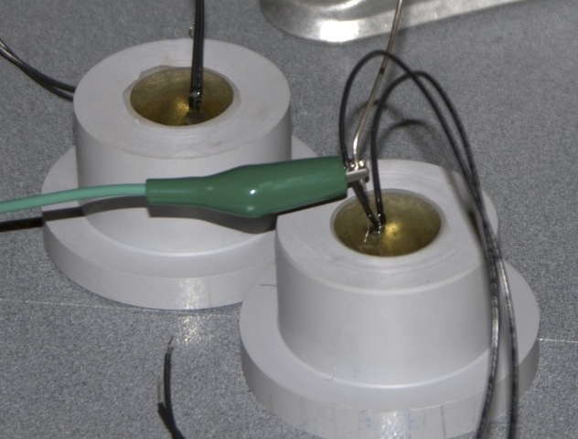
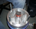
The E-Stop was fairly simple and used a similar construction as the fin bushings.
The wires of the reed switch should have been protected, we broke them off in one of the vehicles.
Battery Module
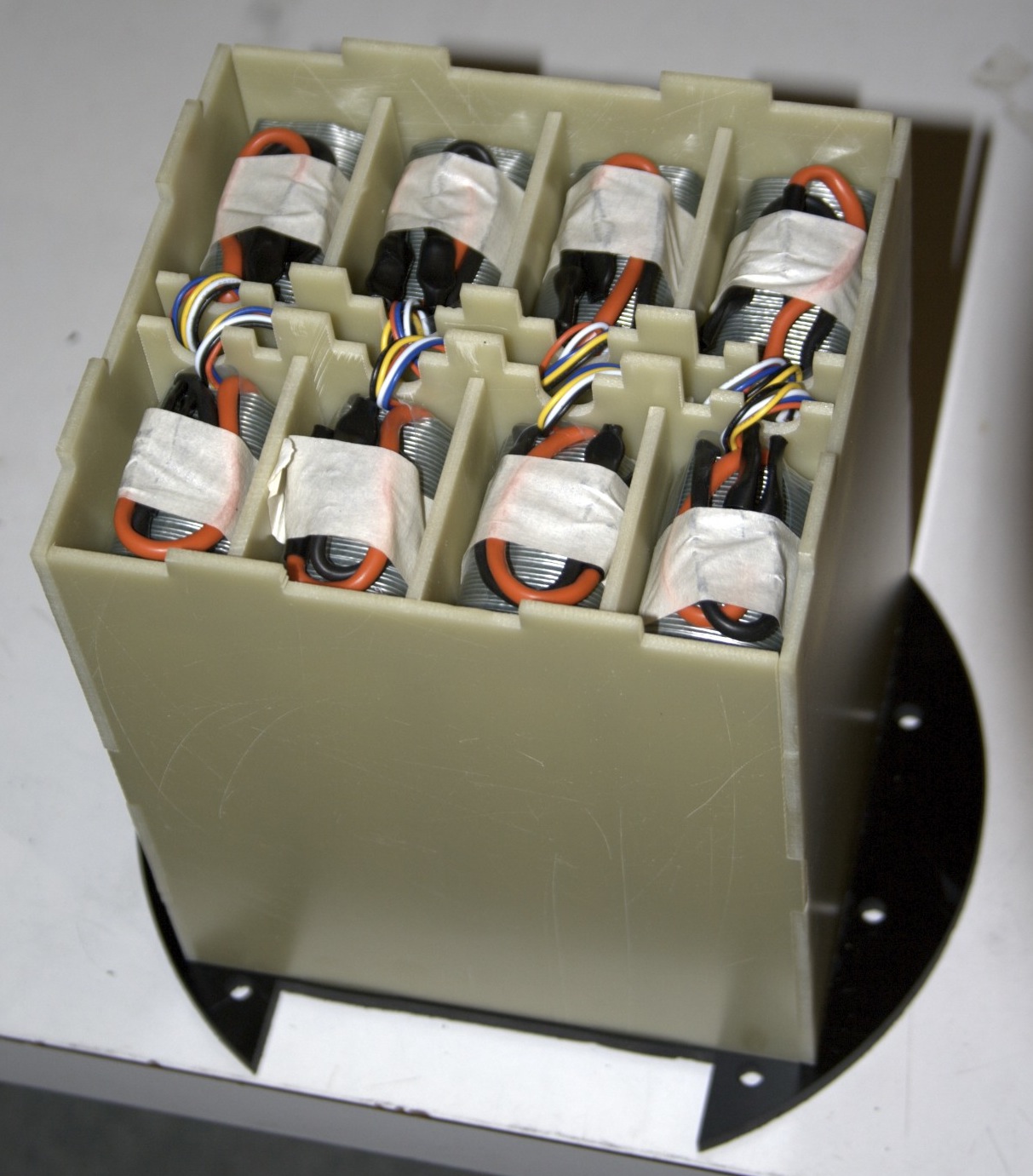
The battery pack was composed of eight 31321 All-Battery Lithium Polymer packs. The packs contain 3x8AHr cells. The module was constructed of 1/8th inch watterjetted FR4.
The balancers and chargers came from Astroflight, numbers 106 and 109 respectively.
An additional cell was used to power the logic, the main pack was only used for the drive motor. The drive motor was galvanically isolated from all other systems.
The chargers and balancers seemed to work appropriately, they unfortunately did not warn of over discharge and we damaged several logic batteries as a result. We grafted the ability to monitor those voltages into the system as a result.
We had no issues with battery life. We did not run into battery lifetime issues though we suspect it will become an issue in the future.
Electronics
The electronics on the vehicle were fairly straight forward with the exception of the motor controller and other high power electronics.
The system was driven by a Freescale HCS12 on a development board from Image Craft (#CardS12.XDP5). We made a simple daughter card to provied convenient connectors and a power supply.
The initial plan was to have several of these cards – all connected over a CAN bus. We planned to have a card in the rear with the motor controller, one with the batteries to monitor cell voltages and temperatures, one with the payload, and finally a “master” to handle pose estimation and control.
Time and manpower constraints cut all cards except for one – the master. There was no battery monitoring save logic voltage. No “real” pose estimation ran on the production vehicle. No control algorithms ever ran on the production vehicle (they were written – though never tested) because we were unsure of their effectiveness – and a little scared of what they may do. Lesson learned – write a kinematic simulator to develop control algorithms.
The was the system worked was it had a menu based serial console which listened on two serial ports – one connected to the debug connector and the other connected to a serial to ethernet converter. The serial to ethernet conterter was from Lantronics (XP100200K-03). We got the dev kit.
There were two ways to communicate with the vehicle – over fiber through the network or directly through RS-232 and the debug port. The fiber was preferable because it was longer and lighter than the cable which was short and sank like a stone.
The fiber worked well, and we never had a problem with the fiber to ethernet converters (Newegg TFC-110MSC). We used a standard Linksys wireless router, and could communicate wirelessly with the vehicle during testing above water.
For sensing we had a pressure sensor (SSI Technologies P51-51-A-B-I36-4.5V-R), an Analog Devices IMU (ADIS16360-BMLZ) and a tilt compensated compass (Sparkfun HMC6343). All sensors were largely unused – see comments about system modeling.
Various voltages for the vehicle’s logic, sensing and communications systems were produced by a slew of Texas Instruments programmable switching power supplies (PTN78020WAH).
Motor Controller
The motor controller (low side – unidirectional) was an Alltrax AXE7245 from Cart Zone which was switched by a 101-EV200HAANA contactor from EV Source.
I wanted an isolated SPI D/A converter to drive the motor controller (analog voltage input). Instead Kevin developed a ladder of discrete opto-isolators and a resistor network to give eight motor steps where 0 is off and 7 is full speed. These discrete steps combined with programmable ramping in the motor controller worked fine for our purposes.
Cabling
We chose to make all of the cabling inside of the vehicles DB9 and we made all of the cables ourselves – this was a colossal pain in the a$$. A better call would have been to use CAT5 and R45s or crimp rather then solder cup DB9s. Regardless we found some good parts for the cabling (Digikey part numbers follow).
- DB9 cable side female – 209FE-ND
- DB9 bulkhead side male – 209ME-ND
- DB9 backshell straight – 970-09BCA-ND
- DB9 backshell 45° – 970-09BCA-ND
- DB9 bulkhead mounting hardware – 160-16F-ND
For logic power, we used a connector called 2W2 manufactured by Conec. It fit into a normal DB9 hole and had two large contacts which fit up to eight gauge wire.
- 2W2 Conec male – 626-1095-ND
- 2W2 Conec female – 626-1094-ND
- 2W2 Conec female pin – 626-1141-ND
- 2W2 Conec male pin – 626-1145-ND
For the drive motor, we used high strand four gauge wire and large Anderson Powerpole connectors (SB175) from Powerwerx.
Coupler
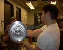
The coupler which connects the forward and aft sections is machined from 6061 10 inch diameter aluminum tube.
The tolerances of the machined tubes were a little suspect. One tube was a tight press fit into the forward hull while the other was rather loose. Using several (5+) tubes of (previously mentioned) Devcon epoxy it was securely attached.
The aluminum coupler’s mating surfaces were coated with a layer of epoxy which was allowed to gel up. More epoxy was applied and the coupler was pressed into the PVC hull. It worked very well.
The o-rings on the coupler were initially sized a little large, and after buying a large selection of rings, we made it work. Due to manufacturing tolerances on our part, different o-rings were required for each vehicle.
See the Parker O-Ring handbook
Rear Assembly
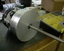
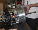
The rear assembly is where the steering and propulsion systems were housed. It was a fairly complex. In this assy, four servos and a 30hp (nominal) golf cart motor was crammed.
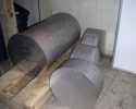
We (I) spent quite a bit of time refining the rear plate. The rear plate was machined from a billet of aluminum. The billet started out as a 12″ diameter, six foot long cylinder. We diced it up using the horizontal bandsaw and the crane.
The whole project was right on the edge of the capacity of our machine tools – I was also the senior machinist on the project. We had to send the blanks out to GTRI to get roughed down to a diamater I could machine (we didn’t have a big enough lathe). Then, after they were roughed out, I spent a few days, maybe around 60 man hours, pocketing the bulkheads to reduce weight. A fairly ridiculous endeavor – for not too much gain.
Program Results
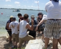
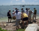
The vehicle weighed in at 300 or so pounds and was quite unwieldy. It was quite a chore getting it in and out of the water. Particularlys, the fins were quite fragile and there was concern that damage to the fins may also damage their seals leading to leakage.
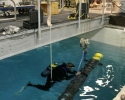
Two vehicles were completed which could effectively transport the specified payload to the target from the desired range at the desired speed. While only one vehicle was tested, the vehicle reached speeds in excess of sixteen knots with a high degree of accuracy.

